
Phygital @ ART+COM
Building a small wireless sensor for a prototyped “Phygital magazine”
Preface
The goal of the described project is to build a small short-distance wireless sender equipped with a touch or light sensor that can be hidden in a printed magazine / book to make it “Phygital” = Physical and Digital. Two use-cases have been implemented:
- The user sees a printed advertisment with an integrated touch area. If he touches the area on the paper, the corresponding product is offered on a nearby screen and can be customized by the reader.
- The user opens a book and the reading light switches oh while the ambient light dims down.
Requirements
- Small size
- As simple as possible
- Maintenance free
- Power efficient
- Fast reaction on user action
- No LiPo batteries because of fire hazard while charging them (especially between paper)
Wireless technology
The follwoing criteria were taken into account when choosing the wireless technology:
- Communication needs to be uni-directional only
- No sensitive data is transferred. Data encryption is not neccessary
- The distance between sender and receiver is just a few meters
- The sender hardware should be small
- The technology must be legal and licence free
- No constant connection to base station (like WiFi or Bluetooth) to save energy
- No time consuming handshakes to establish a connection
We’ve chosen a very simple 433Mhz ASK-Modulated technology, often called “RF433”. They are very similar to the 433Mhz wireless modules used for wireless power outlets, for cheap headphones, simple doorbells etc. They work nearly like a wire - they just transmit the level on the transmitter’s input pin to the receiver’s output pin. In an ideal world, we could just use them as wire and connect them to the UART-pins of the microcontroller. That even works sometimes, but is not reliable enough. It needs a protocol that deals better with the specific characteristics of wireless transmission.
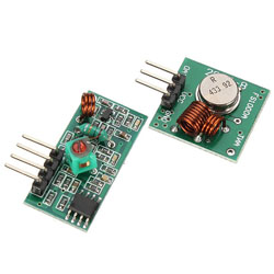
RF 433 sender and receiver
The whole transmitting logic is simple and can be done in software. It has to deal with bad reception and deals with things like sending a preamble to give the receiver a chance to adjust its auto gain control to the signal. Additionally, the data is encoded 4-to-6 bits to achieve a better DC-bias for wireless transmission.
There are a couple of useful libraries for this purpose. VirtualWire, ManchesterTX, RadioHead. We’ve chosen VirtualWire, since it has a small footprint and is well documented. As a nice feature, it handles transmitting via interrupt service routines in the “background” (If we can talk about “background” on a 8 Mhz single core microcontroller ;-) ).
The sender is pretty small. It gives the best range when equipped with a plain lambda/4 wire antenna (17,3cm). It has no power consumption as long as it isn’t transmitting.
Phygital sender
We build two senders. The first is working with resisitive touch, the second has a light dependent resistor to detect if a book is opened or closed. Both are running for 200-300 days with 2 CR2032 coin cells.
Touch sensor with AtMega328 on perfboard.
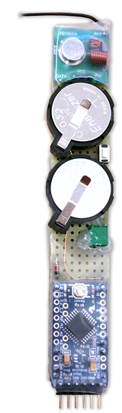
Sender with touch sensor
Light sensor with AtTiny85 on etched PCB.
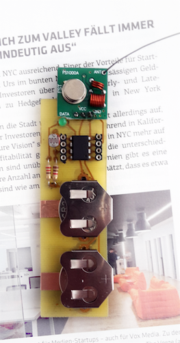
Sender with light sensor
Sender in action
Receiver
The receiver can be powered through 5V USB or PoE. It is connected to the location’s backend via ethernet and builds a bridge to MQTT. It simply forwards received messages to a given MQTT-topic.
Additionally, it has a RGB-LED to show its current state:
- Red: Not connected to network
- Yellow: Connected to network, bootstrapping
- Green: Connected to MQTT-Broker
- Blue: Receiving wireless message
- Flashing pink: Transmitter battery low
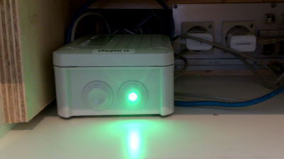
Receiver
Touch
To keep it as simple as possible, we preferred the simplest touch principle - resistive touch between two (nearly) invisible contacts. They are painted with black conductive color onto a black area of the magazine page. Contact is made with self adhesive copper tape on the back of the page. If the contacts are bridged by a finger, the current is enough to wake up the microcontroller from deep sleep.
Light
Light is sensed by a simple light dependent resistor that is read out once a second. The light can be measured through some sheets of paper.
Microcontroller
We used a AtMega328@16Mhz on a Arduino Pro Mini PCB for the touch sender. It is small and can be made very power efficient when removing some parts (Power regulator, Power LED). The board can be powered directly by the CR2032 coin cells. For the second sender, we took a plain AtTiny85 with internal oscillator on a selfmade PCB.
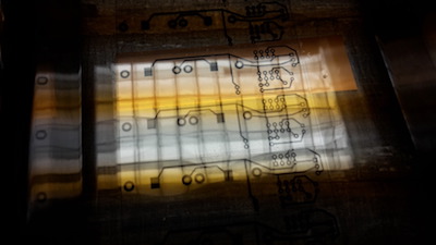
PCB exposure
Power consumption
Sleep modes
Atmel microcontrollers can be very power efficient. It is possible to send them to deep sleep and to disable many integrated units to minimize the power consumption from about 25mA to few micro amperes. They can be activated by interrupts and watchdog timers.
After switching off as much as possible (Analog-Digital-Converter, Brown-out-detection etc.) power consumption went down to 30uA. That gives around 200-250 days of standby time with 2 CR2032 coin cells.
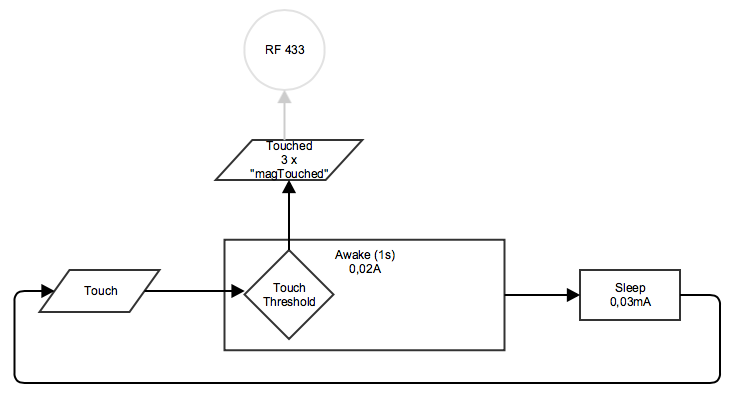
Power states of the sender
Summary
That small project gave me a chance to make some first steps in low-power-land. The technology has been working now for months without problems. The RF433 technology proved to be reliable enough for that use case - but there are now better choices on the market. The new RFM69 modules from hopeFM have the same size - but they provide much more reliabilty, are smaller and have bidirectional transmitting including auto gain adaption, acknowledge-management and AES128 encryption.
For the first sender, we used a complete Arduino Pro Mini and removed some parts to save energy - which hardly makes sense in retrospective. We would rather chose a plain Atmel MCU like AtTiny 85, AtMega32u4 or AtMega328 like we did for the second approach. For easier deployment, we’ll add a software implemented USB-Stack and bootloader to the next sender.