
Mixed Reality - building pipelines, sharing experiences
Mixed Reality is a recently more popular addition to the current XR trend. The very first marketing material of the HTC Vive included Mixed Reality scenes to communicate Virtual Reality - and it makes a whole lot of sense!
VR and AR are currently in a funny state where all enthusiasts want to create content but it doesn’t sell at all. One major reason is communication of the experience - just showing a first person view is very unnatural and the last well known motion video failed horribly (but not for that reason), which was the trashy Doom movie. And that was just a small anecdote to its origins.
Full disclaimer: I wrote my bachelor thesis about building a general purpose mixed reality pipeline, this is a summary of it. You can access the thesis on my personal website.
Table of Contents
- Table of Contents
- 1. Introduction
- Building a Mixed Reality Pipeline (finally)
- Conclusion & Implementation
- Footnotes
1. Introduction
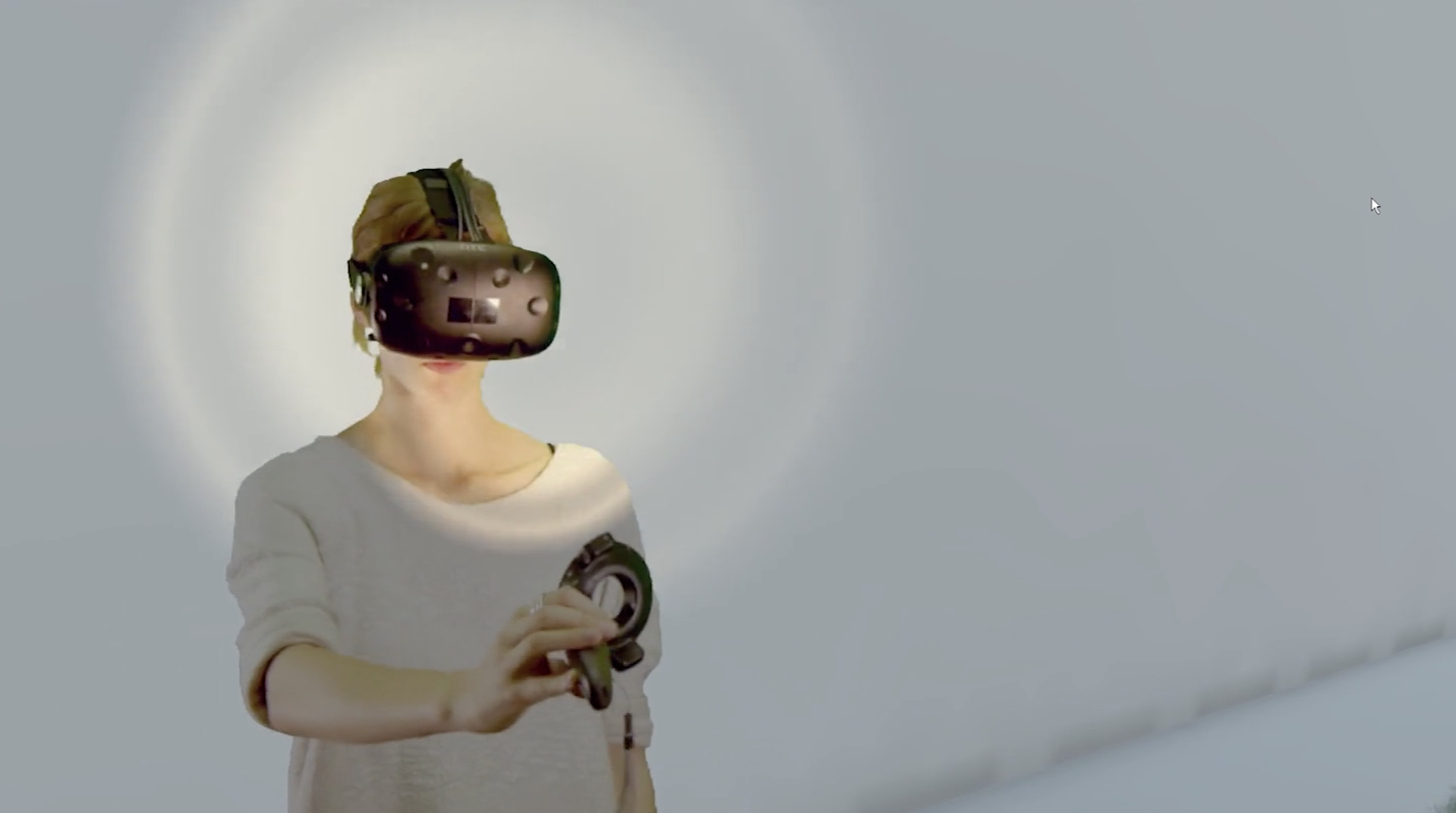
Virtual Reality (VR) is no shared experience. Without putting a headset on yourself it’s almost impossible for someone how the experience feels like to be in VR. As someone who works a lot with VR and AR devices, I’ve got a good feeling how an application works and how it feels with just watching the first person view - but that’s not so true for an executive you’re trying to tell that you’re worth his investment. Additionally, if you ever went to a VR exhibition, you’ll see a bunch of headsets and monitors - it’s downright boring to observe a VR user.
One way of fixing this issue is Mixed Reality (MR) - we simply recontextualize the current user with the virtual surrounding and create an image composition not only what someone sees in a virtual world, but how someone slips into a completely new world.
The presented pipeline is on a single system, is variable in its application and has a reference implementation. It causes a significant performance impact, which has to be considered while developing first.
Prerequisites
We have a few components that are vital in building this:
- a green or blue screen
- a camera
- depending on your camera type, you’ll need an input converter
- a camera tripod is advised
- a VR headset with 6DOF tracking (ie. HTC Vive, Oculus Rift, Acer MR Headsets, etc)
- a recent PC, my system features an Nvidia GTX 1080 with 8GB VRAM
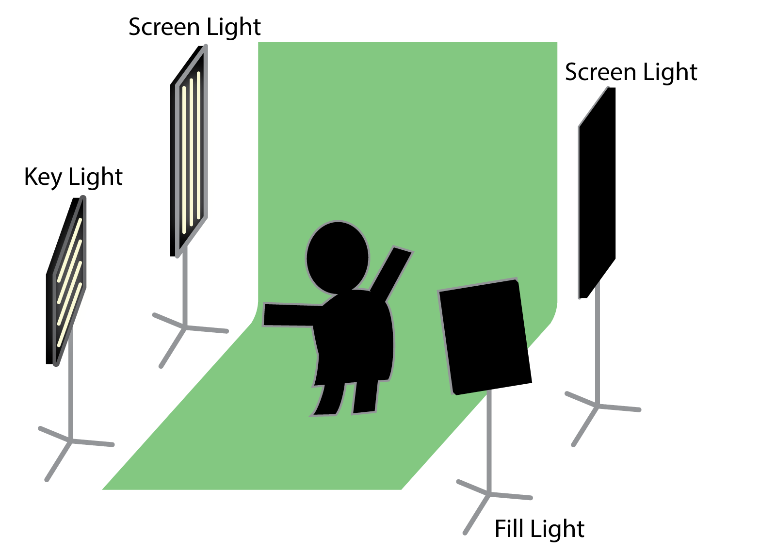
Talking about parts, the green screen is probably the most important one. There
are cheap initial setups on Amazon, which you can get for about €80. In general
you want a matte green fabric with a bit of stretch with some strain on its
mounting points as well as lights for your VR actor and lights on your green
screen. There’s a great book from Jeff Foster going deep into detail
how to, build and work with green screens, if you want to build a really great
set, but in general this schematic should suffice for most purposes:
Your choice of camera is pretty open. In my case, I’ve used a Lumix GH2 paired
with an external INOGENI4kUSB3, which takes any HDMI signal and converts it as
webcam signal - which integrates well into most applications, since webcams are
easily managed by all major systems. Any recent webcam would suffice for a demo,
if you want a fancy option, Owlchemy Labs deploys a
Zed Stereo Camera.
Otherwise your primary goal is to get a noise-free1
signal from a video source into the system you’re running the VR application on.
And from there into your engine.
Otherwise you will need either a tripod or a controller / tracking point of your VR solution. HTC is offering Vive Tracker and Oculus has additional tracker support but not available hardware yet - however, you can hack your own.
Finally you need a PC - since Mixed Reality is mostly a GPU heavy tasks, you need to have some hardware to support that. I’m using a Nvidia GTX 1080, which is sufficient. In general you’re rendering four important cameras, where as two render the stereoscopic view for your headset, one is rendering everything in front of the user and one is rendering behind him. Also you’ll need to store a few framebuffers, so have a few hundred MB of VRAM left.
Assumptions & Considerations
Due to the lack of depth information, you’ll have to assume the actors depth as a plane which is orthogonal to the inverse of the cameras view direction. This means in edge cases, that clipping through geometry will occur - a simple fix for that is to put some work into your shaders and exposing a global depth value in your graphics pipeline.
Doing Mixed Reality is a problem on multiple fronts. One begins with video capturing. You’ll notice a offset between real time and the footage your system received. The general latency is between 50ms - 500ms, which is, assuming 29.97fps content capture, between 2 - 16 frames.2 This is between noticeable to very noticeable ranges.
Finally you should have an artistic vision. Mixed Reality is sometimes unfitting for some applications. Fantastic Contraption decided, that an additional avatar representation is very fitting. The very colorful artstyle is appropiate with a similar stylized avatar instead of a human being. In the end you’re trying to tell a story from a third person view rather than first person, so you might not even need to implement a Mixed Reality pipeline to achieve that goal.
Building a Mixed Reality Pipeline (finally)
Good job on making it that far. Let’s get to the real meat. First of all, here’s a visual representation of the pipeline:
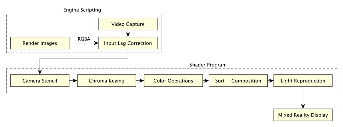
All following headings marked with an * are optional and enhance the visual performance of the final pipeline. You can skip them for an initial implementation.
Virtual Projection Parameters
The missing virtual projection parameters are as following:
- Position of the real world camera relative to the tracking volume
- Rotation of the real world camera relative to the north direction of the tracking solution
- Distance between HMD and real world camera
- Vertical Field of View (vFoV) of the real world camera
Solving for the former two is easy if the camera is mounted on either a controller or a tracker. You probably want to apply an offset to the transformation since you’re solving for the position of the photo sensor inside the camera, which is slightly displaced from the trackers position.
Reconstructing the projection parameters is actually pretty easy, however figuring out the initial variables is hard. For example have most DSLR cameras a cropping factor that is usually not found in specifications. vFoV is calculated with following formula:
// verticalSize is the vertical size of the camera sensor
// focalLength is the length of the cameras focal length
var fov = 180.0 / Math.PI * 2.0 * Math.Atan(verticalSize / (2f * focalLength));
Latency Correction
It won’t matter what camera setup you will use, at some point or another you’ll have to deal with a latency between the received frame of your camera and the real time virtual world. One very simple and feasible solution is to store framebuffer for as long as needed until a camera capture frame is received. This operation is relatively cheap, but costs you a good amount of memory on your GPU to hold these framebuffers. This calculator should give you an impression how much data it is you need to hold temporarily on your GPU:
[(
+
)
x
] x
(
Front +
Back +
Lightning
)
= 0.00MB per frame
fps x
ms x
0.00MB
= MB
In your best case, you’ll need a ring buffer with a fixed size, since the input latency should be a fixed amount of time that you can simply measure. By looking up your cameras specifications you can use following formula to calculate the number of needed framebuffers.
var numBufs = Math.Ceil(fps * (latency / 1000)); // Latency in ms
Thanks to smart usage of the ring buffer, you can now allocate a fixed amount of
frame buffers on your GPU and swap them at any time - this creates no
excess bandwidth and allows for a fixed memory budget that you’ll be able to
measure and access. All that’s left to do is telling your application when to
swap and binding the frame buffers in your shader - both of which can be done
on the same frame.
Now you’ll need to access two buffers at the same time:
- The active frame buffer in which your data gets written into
- The display frame buffer that gets bound into your shader to generate the Mixed Reality composition
Doing that is pretty straight forward - whenever it is time to swap a buffer, you can get and set the buffers accordingly - the next frame buffer after the current index is actually the oldest frame buffer:
index = index % buffer.size;
camera.targetBuffer = buffer[index];
var frameBuffer = buffer[(index + 1) % buffer.size];
material.SetTexture(fieldName, frameBuffer);
Camera Stencil *
One of the most limiting factors in production is the actual recordable space.
Even on professional sets you always have stuff in your way, which will give you
at most a box with three sides, bottom and top. On amateur sets you usually have
one to two sides and only the bottom. The problem arises once the camera films
outside the boundaries, resulting in non-greenscreen pixels - literally garbage
pixels. Luckily you’re already in a real time 3D engine, which allows you to
rebuild the boundaries of your set. Since OSVR and other libraries usually
assume that 1 unit = 1 meter, you can rebuild your real world set and
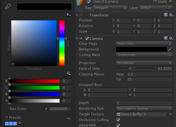
the real world environment easily. Add the set to a culling layer and clear the
camera on RGBA(0, 0, 0, 0). Every pixel which will be inside your
greenscreen will have an alpha value of 1, which lets you transfer that
alpha mask directly onto your camera image:
Sampler2D cameraImage;
Sampler2D alphaMask;

fixed4 frag(v2f i) : SV_Target {
  fixed4 cameraPixel = tex2D(cameraImage, i.uv);
  fixed  alphaPixel  = tex2D(alphaMask, i.uv).a;
  cameraPixel.a = alphaPixel;
  // ... other stuff
}
In Unity such a setup would look like that:
Chroma Keying
Alright, so we have done a bunch of easy tasks now - but let’s get to one of the
main parts to solve for on your GPU. The basic problem is, that we have three
color channels in our input signal and want to pull the alpha matte from it.
This is most easily done by having a keying background color and taking that as
reference for our alpha value. So we’re approximating a fourth color channel by
taking all of our input channels and trying to extrapolate a completely new one.
Most commonly this is done with help of CIEDE1976, as it is very cheap computational wise and yields very similar results than CIEDE2000. It is slightly incorrect from what the Color Consortium currently suggest for calculating color distances - but it’s good enough for our purposes.
The most basic and brief theory for that you need to know:
We have a three-dimensional vector RGB, which is influenced on how humans
perceive colors. It is possible to calculate a normalized three-dimensional
vector in the Lab color space, that resembles the “real” color more closely.
Then you take the distance between your green (in Lab) to the pixel color of the
camera image (in Lab, too). From there you assign all distances between a lower
and upper limit between 1.0. Et voilà, you have alpha values for each discrete
pixel in your image.
The HLSL implementation can be found in this public gist. Note
that even if we have already figured out that the camera stencil gives an alpha
value of 0, it is necessary to run the chroma operation, since there is no early
out for this operation.
Explore the differences in color rooms with this handy tool by @franciscouzo:
Color Operations *
By now we have enabled an alpha-mask for our camera image. Hopefully all pixels that depict the background are removed, so it’s a good time to modify the camera image to fit better into the scenery. Since we’re compositing way beyond the 3D pipeline, we have to do these transformations manually per pixel. Luckily all these operations are not so complex.
Spill Removal
Sometimes the green background will spill onto the actor, giving the pixels a green tint. By using an HSV color wheel and shifting all pixels towards the opposite direction of the keying color, you will reduce the tint while not rotating all colors. Otherwise you would fix the tint by rotating, which would make most of the actors clothing look different than what you perceived as “normal”.
float3 spillRemoval(float3 rgb, float3 targetColor, float weight) {
    float2 target = rgb2ycgco(targetColor.rgb).yz;
    float3 ycgco = rgb2ycgco(rgb);
    float sub = dot(target, ycgco.yz) / dot(target, target);
    ycgco.yz -= target * (sub + 0.5) * weight;
    float3 col = ycgco2rgb(ycgco);
    return col;
}
Brightness
This one is easy, since it just increases each color channel by a value b:
float3 brightness(float3 rgb, float n) {
    return rgb + b;
}
Contrast
The color channel will be decreased by half and multiplied with a contrast
factor c:
float3 contrast(float3 rgb, float c) {
    return (rgb - 0.5f) * c + 0.5;
}
Saturation
To (de)saturate an image, you will need to calculate the color intensity and
then lerp it with a saturation factor s:
float3 saturation(float3 rgb, float s) {
    float3 intensity = rgb * float3(0.2126f, 0.7152f, 0.0722f);
    return lerp(rgb, intensity, s);
}
Sort & Composition
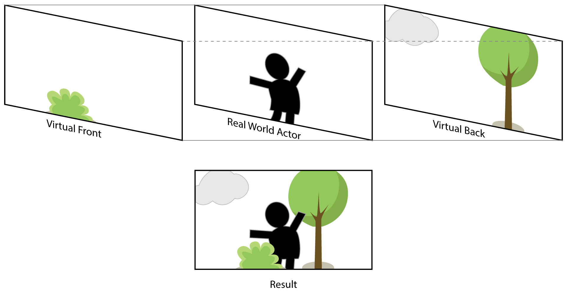
In compositing an image there is a choice between accuracy and compatibility. Deferred shading can easily change depth- and alpha maps for correct projections and therefore are invalid for the assumption we make in compositing the image. The options we have here are:
- Replace Masking:
A front plane is displayed, after it follows a chroma-keyed video and then the virtual background. This is the most accurate image generation, if the front image is generated correctly and not modified by post effects or deferred shading. - Alpha Masking:
A front alpha mask of the geometry is being generated, then the actor is mixed with a full render image of the scenery’s background. The resulting image has inconsistencies with alpha-blending but this method works with all rendering setups.
Replace Masking
With a generalized matting equation, we’re needing an alpha-transparent front, the extrapolated alpha-matte from the video feed and the background, which we then can mix as following:
float4 mixCol(float4 upper, float4 lower) {
    // total alpha value after mixing both layers
    float mixAlpha = median.a * (1 - front.a);
    return front * (1 - mixAlpha) + median * mixAlpha;
}

sampler2D frontTex, webcamTex, backTex;
fixed4 frag(v2f i) : SV_Target {
    fixed4 front  = tex2D(frontTex,  i.uv);
    fixed4 webcam = tex2D(webcamTex, i.uv);
    fixed4 back   = tex2D(backTex,   i.uv);
    /* do all previous steps, including chroma keying and then... */
    // squash the front and camera together on the front
    front = mixCol(front, webcam);
    // and finish the composition
    return mixCol(front, back);
}
Alpha Masking
Alpha masking is basically rendering the front geometry and clearing the camera in similar fashion like the stencil projection. This will yield an alpha mask of all front pixels, which can be transferred to the webcam footage, thus allowing us to mix the background with the webcam - while the background already consists of the virtual foreground. Most noticeable is that transparent geometry will be incorrectly mixed with the webcam footage.
sampler2D frontTex, webcamTex, backTex;
fixed4 frag(v2f i) : SV_Target {
    fixed front   = tex2D(frontTex,  i.uv).a;
    fixed4 webcam = tex2D(webcamTex, i.uv);
    fixed4 back   = tex2D(backTex,   i.uv);
    /* do all previous steps, including chroma keying and then... */
    // transfert the inverted alpha mask:
    // + geometry will have an alpha value of 1
    // + webcam should have then an alpha value of 0
    webcam.a = 1 - front;
    // and finish the composition
    return mixCol(front, back);
}
Light Reproduction
One final step before finishing the composition is left: Light reproduction.
Since we already agreed, that the actor is flat as a plane in 3D space we can
use that assumption to build a light-capturing white plane, place it inside the
the scene with the depth of the headset and yield a rendering of the current
lighting environment at the planar space where the actors video footage will end
up. This increases immersion and makes a natural fit for mixed reality.
Since we reconstructed the depth between real world camera and real world headset before, we can simply calculate a plane big enough to fit inside the camera frustum:
var pos = camera.position + Z * camera.forward;
var scale = 2 * Mathf.tan(camera.fov / 2) * Z;
var localScale = new Vector2(scale, scale * 16f / 9f);
Now we can use our shader again, bind another sampler2D and have a untainted
capture of the lighting environment. This one can be multiplied to the webcam
signal after all color operations have been done on it.
Finishing the shader
Now we can assemble all pieces with all previous methods, hiding all the
less-nice parts behind cginc files.
flaot4 webcamTex_TexelSize;
sampler2D frontTex, webcamTex, backTex, lightTex, stencilTex;
fixed4 targetColor;
float4 sBCS; // spill, brightness, contrast, staturation factors

fixed4 frag(v2f i) : SV_Target {
    fixed4 front   = tex2D(frontTex,   i.uv);
    fixed4 webcam  = tex2D(webcamTex,  i.uv);
    fixed4 back    = tex2D(backTex,    i.uv);
    fixed4 light   = tex2D(lightTex,   i.uv);
    fixed4 stencil = tex2D(stencilTex, i.uv);
    // inverse of the "stencil"
    webcam.a = 1 - stencil.a;
    // chroma keying
    webcam.a = chromaKey(webcam, targetColor);
    webcam.rgb = spillRemoval(webcol.rgb, targetColor.rgb, sBCS.x);
    webcam.rgb = colorOp(webcol.rgb, sBCS.yzw);
    front = mixCol(front, webCol * light);
    return mixCol(front, back);
}
Conclusion & Implementation
One of the problems I have yet to investigate throughout and write a well working solution for is calibrating the offset between the camera and the controller. Serious Sam VR uses a back-propagation of transform matrices, other use object tracking. In a perfect world, I’d like to have an approach where you can hold a controller (or headset) in front of the camera and with computer vision techniques it should be possible to get pretty well fitting results from that. Realistically it’s something between OpenCV checkerboards and my idea - which would make the headset / controller look somewhat hideous.
While building this pipeline, I used Unity3D - which was not without issues.
Regardless, it was a fun excersize in building a general purpose pipeline that
is applicable to all sorts of engines, render backends and devices. From there
it’s possible to port that for other AR/VR cases and have a good platform to
tweak and expand upon for more experiences. The “in progress” repository can
be found in the Components repository. There’s a bunch of different
steps and progress to be found, as well as application helpers and an unfinished
UI.
A Unity package, as well as the source code and a prefab for quick
implementation can be found in ART+COMs repository.
Footnotes
1: I am aware that there is no such things as a noise free
signal. ↩
2: Latency is rounded up. ↩